


The previous part of this lesson describes the relations between the video, image, pixel, and color, and also introduces two popular types of color spaces. One is RGB color, which is widely known, and the other is YUV color, which is frequently used for videos. This part will introduce more about the RGB and YUV color spaces. You can learn about the common sampling and storage formats adopted by the two types of color spaces.
The sampling and storage formats of colors affect how images are processed. An image can be presented as expected only if we process the image in a proper way.
Sampling and storage formats of RGB
We already know that an image is composed of pixels, and pixels present various colors by recording components of the color space. For the RGB color space, the three components R (red), G (green), and B (blue), have interconnections and are all indispensable for color representation.
Therefore, each pixel records the three components at a sampling rate of 1:1:1. This rate shows the relation between the number of samples rather than the values of the three components. Such sampling rate brings difficulties for data compression of RGB. Therefore, RGB is not suitable for encoding and transmitting video image data.
The three components are stored sequentially in the memory after sampling. However, they may not be stored in the order of R > G >B. The storage order may vary based on specific scenarios and processing logic. For example, the order is R > G > B in MATLAB and B > G > R in OpenCV. The following figures show the differences:

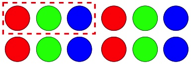

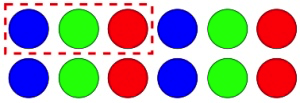
The order used to describe the R, G, and B components in a literal way is called the literal order, and the order that is used to describe how R, G, and B components are stored in memory is called the byte order. Before you process an image, you must determine the byte order of the color space components. If the stored components are not read based on the correct byte order, the image color may not be as expected after processing. The following figure shows the problem in image colors due to byte order mismatch.
You may also know other storage formats, such as BGRA. The BGRA format can be used to process camera data on devices that use the iOS or macOS system. RGBA stands for red, green, blue, and alpha. The alpha color channel is used to specify the opacity for color and helps present richer color effects. For the RGB format that adds an alpha color channel, the storage order of the components is still important. Common formats based on the storage order include BGRA, RGBA, ABGR, and ARGB.
This part does not provide a further explanation of the sampling and storage formats of RGB because they are relatively easy to understand. The previous part of this lesson mentioned that YUV is the most popular color space for video processing. The sampling and storage formats of YUV are more complex than those of RGB.
Sampling and storage formats of YUV
YUV sampling formats
Unlike the RGB color space, not all three components of the YUV color space are involved in the representation of colors. The Y component alone, which indicates the luminance, can still present the image with black, white, and gray colors. The human eye is not highly sensitive to the two chrominance components U and V. Therefore, the image effect is not affected if the U and V components are removed in a small proportion. This feature allows fewer samples of the U and V components to achieve high data compression through sampling. In some cases, you can even specify that U and V components are not sampled to present black-and-white images. Sampling formats of YUV can be classified based on the sampling rules for the U and V components. Common YUV sampling formats include YUV 4:4:4, YUV 4:2:2, and YUV 4:2:0.
The formats above can be written as YUV A:B:C. You may think that Y:U:V equals A:B:C, representing the sampling rate of Y, U, and V. It is not correct actually. A:B:C does not represent the sampling rate of the three components. In fact, in a sampling area with a width of A pixels and a height of two pixels, the U and V components are sampled as a whole, and a ratio is given to describe the UV samples relative to the Y samples.

To help you understand the sampling logic, see the rules converted based on the sampling logic of YUV A:B:C below.
- A sampling area with a width of A pixels and a height of 2 pixels, namely two rows and four columns, is defined.
- In the first row, the number of Y samples is A, and that of the UV samples is B.
- In the second row, the number of Y samples is A, and that of the UV samples is C.
- If C is 0, the U and V components are not sampled in the second row. The second row reuses the UV samples of the first row.
Now, let’s understand common YUV sampling formats based on the preceding rules.
The first one, YUV 4:4:4. The rules are as follows:
- A sampling area with a width of 4 pixels and a height of 2 pixels is defined.
- In the first row, the number of Y samples is 4, and that of the UV samples is 4.
- In the second row, the number of Y samples is 4, and that of the UV samples is 4.
Figures can also help us understand the sampling logic. The following figure shows the sampling logic of the YUV 4:4:4 format. In the figure, hollow circles represent Y samples, and filled circles in blue represent the UV samples. The colors in the figure do not indicate the colors of actual samples.
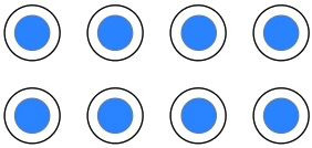
Based on the preceding explanations and the figure, we know that in the YUV 4:4:4 format, each Y sample corresponds to a set of U and V samples. This indicates that no downsampling is conducted for the U and V components compared with the Y component both in the horizontal and vertical directions. In this case, the ratio of Y samples and UV samples is 1:1, which means that each pixel contains the luma component and chroma components.
The YUV 4:4:4 format is relatively easy to understand. Next, let’s move to YUV 4:2:2.
The rules of the YUV 4:2:2 format are as follows:
- A sampling area with a width of 4 pixels and a height of 2 pixels is defined.
- In the first row, the number of Y samples is 4, and that of the UV samples is 2.
- In the second row, the number of Y samples is 4, and that of the UV samples is 2.
The following figure displays the sampling logic:
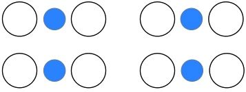
In the figure above, downsampling is conducted for the U and V components in the horizontal direction. Therefore, every two Y samples in the horizontal direction share one UV sample. In this case, the ratio between Y components and UV component sets is 2:1. Downsampling is not conducted in the vertical direction. The second row follows the sampling logic of the first row, which means two sets of U and V components are sampled in the second row. Obviously, the total quantity of UV samples in the YUV 4:2:2 format is lower than that in the YUV 4:4:4 format because of the downsampling in the horizontal direction. However, thanks to the characteristics of YUV, the image color is hardly affected. This is helpful for the compression of sampled image data with high fidelity ensured.
We have now learned the sampling logic of the YUV 4:4:4 and YUV 4:2:2 formats. However, you may still doubt that the equation Y:U:V = A:B:C is correct because the YUV 4:4:4 and YUV 4:2:2 formats seem to conform to the principle of this equation. Are we drawing a wrong conclusion to this equation?
The answer is no. We still have one YUV sampling format, YUV 4:2:0, to introduce.
If we follow the principle of the equation Y:U:V = A:B:C, YUV 4:2:0 means that the Y and U components are sampled at the ratio of 4:2, while the V component is not sampled. This conclusion is wrong. In the YUV 4:2:0 sampling format, Y, U, and V components are all sampled, and the U and V components are still sampled as a whole. To help you understand this, we can analyze the YUV 4:2:0 format in the same way.
- A sampling area with a width of 4 pixels and a height of 2 pixels is defined.
- In the first row, the number of Y samples is 4, and that of the UV samples is 2.
- In the second row, the number of Y samples is 4, and that of the UV samples is 0.
- The second row reuses the UV samples of the first row.
Different from the YUV 4:2:2 format that conducts downsampling only in the horizontal direction, the YUV 4:2:0 format conducts downsampling both in the horizontal and the vertical directions. The second row reuses the UV samples of the first row rather than sampling new sets of U and V components.
The following figure shows the sampling logic of the YUV 4:2:0 format:
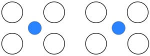
The figure shows that in the horizontal and vertical direction, every four Y samples (a 2×2 sampling area) share one UV sample.
Now, you may have a deeper understanding of the YUV 4:2:0 sampling format and know why the Y:U:V = A:B:C equation is wrong. In addition, the number of UV samples in the YUV 4:2:0 format is smaller than that in the YUV 4:2:2 format. Therefore, we can also infer that the image data can be further compressed using the YUV 4:2:0 format.
Other common YUV sampling formats such as YUV 4:1:1 are not introduced in this part. As long as you master the principle of A:B:C, you can have a quick understanding of other YUV sampling formats with ease. All YUV sampling formats have one common feature: The luminance component Y is sampled in every pixel, but one chrominance component set UV may be shared by N pixels, which makes a difference in the amount of sampled data.
At this point, we have learned about the YUV sampling formats. The right sampling format is vital for processing YUV images. If the sampling format that you choose is improper, the image will not be as expected after processing.
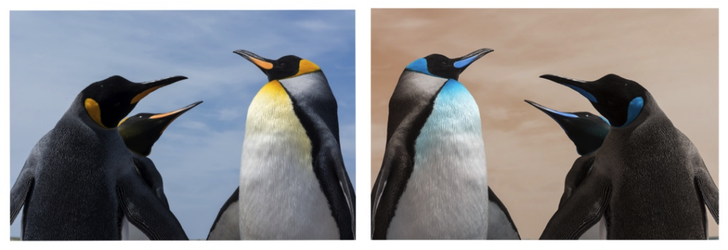
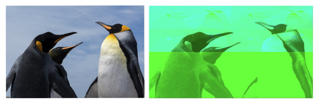
The following figure shows the abnormal color effect of an image in the YUV 4:2:0 format when the YUV 4:4:4 format is used to read the image.
Except for the sampling formats, we also need to know how YUV components are stored. There are many YUV storage formats, and one sampling format can be used with different storage formats. Different YUV formats adopt different combinations of sampling and storage formats. You may have difficulties in understanding and remembering these YUV formats. The sections below can help you understand them.
YUV storage formats
When we introduce the storage formats of the RGB color space, we focus on the arrangements of each component in memory, and learn about two storage formats defined based on different storage orders, namely RGB and BGR. We can also follow this logic to understand YUV storage formats.
Here, we introduce arrays to represent a storage structure of YUV formats, which is called plane. We use an array to represent a storage plane, and N different arrays indicate N planes. YUV storage formats can be classified into the following three categories based on the storage order of components and the number of planes used: packed format, planar format, and semi-planar format.
The rules of each storage format are as follows:
- Packed format: One plane is used for storage. On this plane, the Y, U, and V components of each pixel are packaged and stored in a consecutive and interleaved way.
- Planar format: Three planes are used for storage. The Y components of all pixels are consecutively stored on the plane 1. The U components of all pixels are stored on the plane 2. The V components of all pixels are stored on the plane 3. The plane 2 can store either the U or V components, which is the same for plane 3.
- Semi-planar format: Two planes are used for storage. The Y components of all pixels are consecutively stored on the plane 1. The U and V components of all pixels are stored on the plane 2 in a consecutive and interleaved way.
The rules clearly describe the logic of YUV storage formats. Now, let’s take a look at how sampling formats work with storage formats. A sampling area with a width of 4 pixels and a height of 2 pixels is defined to facilitate understanding.
Storage formats for YUV 4:4:4
The sampling logic of YUV 4:4:4 is simple, and its storage formats are also easy to understand. The following figure shows the storage logic of the packed format used for the YUV 4:4:4 sampling format in a 4×2 sampling area.
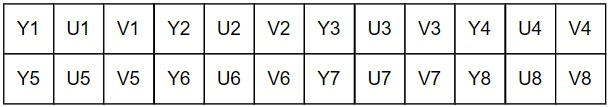
Only one plane is used in the packed format. This plane can be regarded as a 12×2 array.
The following figure shows the storage logic of the planar format used for YUV 4:4:4.
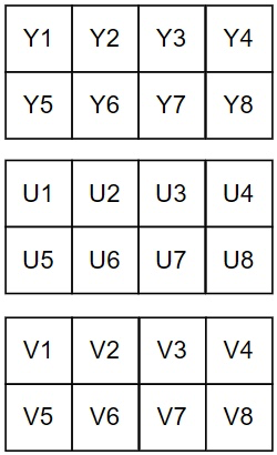
Compared with the packed format, the planar format uses three planes for storage. The Y, U, and V components are separately stored on three planes. Each plane is a 4×2 array. If the storage order is Y > U > V, this YUV format is called I444. If the order is Y > V> U, this format is called YV24.
The following figure shows the storage logic of the semi-planar format used based on the YUV 4:4:4 sampling format.
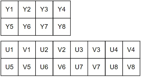
Two planes are used in the semi-planar format. One plane stores the Y components, and the other plane stores the U and V components. The Y plane is a 4×2 array, and the UV plane is an 8×2 array. If the storage order of U and V components is U > V, this YUV format is called NV24. If the order is V > U, this format is called NV42.
The preceding section introduces the YUV formats that adopt different storage formats for the YUV 4:4:4 sampling format. In the next section, we will introduce more YUV formats based on the YUV 4:2:2 and YUV 4:2:0 sampling formats.
Storage formats for YUV 4:2:2
The sampling logic of YUV 4:2:2 is discussed in the preceding section. In short, Y components are fully sampled. In the horizontal direction, every two Y components share one set of U and V components. In the vertical direction, UV component sets are independently sampled for each row. You can review the related content in the section YUV sampling formats if you still have questions.
The following figure shows the storage logic of the packed format used for the YUV 4:2:2 sampling format. Each UV component set in light blue is shared by the left-side and right-side Y components.
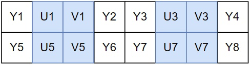
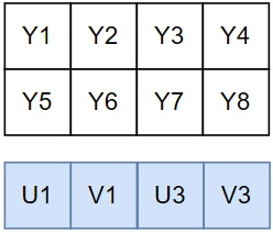
In the packed format, the only plane is an 8×2 array. The components are stored in an order of Y > U > V > Y, which means every two Y components share one set of U and V components. This format is called YUVY. Similarly, more YUV formats can be defined based on the storage order of components in the packed format, such as VYUY and UYVY.
The following figure shows the storage logic of the planar format used for YUV 4:2:2.
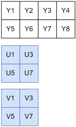
In the planar format, the three planes are 4×2, 2×2, and 2×2 arrays, respectively. If the U components are stored on plane 2 and V components on plane 3, this format is called I422. If the V components are stored on plane 2 and U components on plane 3, this format is called YV16.
The following figure shows the storage logic of the semi-planar format used for YUV 4:2:2.
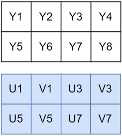
In the semi-planar format, the two planes are 4×2 arrays. If the storage order of U and V components is U > V, this format is called NV16. If the order is V > U, this format is called NV61.
Storage formats for YUV 4:2:0
Now, let’s move to the storage formats for the most commonly used sampling format YUV 4:2:0. YUV 4:2:0 mainly adopts the planar format and semi-planar format for storage.
The sampling logic of YUV 4:2:0 is introduced in the preceding section. In short, the Y components are fully sampled. In the horizontal and vertical directions, every four Y components share a set of U and V components. You can review the related content in the section YUV sampling formats as needed.
The following figure shows the storage logic of the planar format used for YUV 4:2:0.
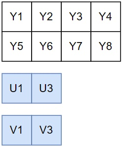
In the planar format, the three planes are 4×2, 2×1, and 2×1 arrays, respectively. If the U components are stored on plane 2 and V components on plane 3, this format is called I420. If the V components are stored on plane 2 and U components on plane 3, this format is called YV12.
The following figure shows the storage logic of the semi-planar format used for YUV 4:2:0.
In the semi-planar format, the two planes are 4×2 and 4×1 arrays, respectively. If the storage order of U and V components is U > V, this format is called NV12. If the order is V > U, this format is called NV21.
By now, we have learned about the YUV formats that adopt different storage formats for common YUV sampling formats. Among these YUV formats, the NV21 format is used by cameras on Android devices, and the NV12 format is used by cameras on iOS and macOS devices. The preceding section also mentions that the BGRA format is also used by cameras on iOS and macOS devices. You can acquire a basic understanding of these formats at first because you may have chances to deal with these formats.
To process a YUV image in a correct way, we must determine the storage format of the image in advance. If we use a wrong format, the image color will not be as expected. This is also true for dealing with an RGB image.
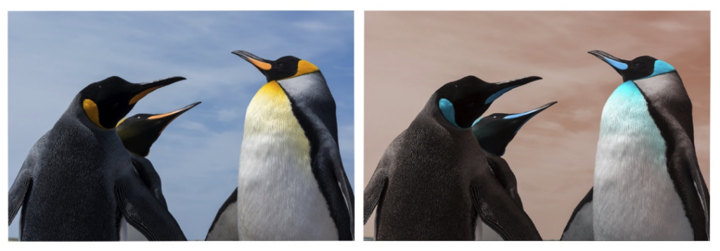
The following figure shows the comparison between two images. The left-side original image is in the I420 format that adopts the planar format and stores the U components on plane 2 and V components on plane 3. The right-side image is generated when the original image is read based on the YV12 storage format that adopts the planar format and stores the V components on plane 2 and U components on plane 3.
Left-side image: original image in the I420 format Right-side image: image generated using the YV12 format
Summary
Compared with RGB formats, the YUV sampling and storage formats are complex, and the generated YUV formats are numerous. You may wonder how to remember these formats.
Actually, you do not have to remember detailed information about a specific format. You can refer to the relevant information when you use it. What you need to do is to fully understand YUV sampling formats and storage formats. On this basis, you can analyze any type of YUV formats by determining the sampling format, the storage format, and the storage order of the U and V components. As mentioned earlier, as long as you master the logic of YUV formats, you can have a quick understanding of different YUV formats with ease.
Let’s Build APP Together
Start building with real-time video, voice & chat SDK for apps today!
