


In the previous two articles, we discuss the relationships among color spaces, pixels, images, and videos. We also talk in detail about the sampling and storage formats for a red, green, and blue (RGB) color space and a luma, blue projection, and red projection (YUV) color space. In this article, we add some important knowledge about these topics.
As we know, a pixel is the smallest element in an image. Therefore, the storage of video images is essentially the storage of pixels. When computers process images, they read pixel data from memories based on specific rules. The rules are formulated based on how colors are sampled and stored. The rules define the sequence to store the data of color components and the logic to store the data on a different number of planes. However, if the rules contain only this information, computers can hardly understand how to read pixel data. The rules must also define the number of bytes of data to be read. For this purpose, quantifying rules need to be formulated.
Image bit depth
To understand how data of video images is stored, first, we have to know how each pixel is stored in a computer in a quantitative manner. Here, we introduce the concept of image bit depth.
This concept is not alien. In previous articles about audio, we have talked about audio bit depth, which is used in audio sampling. Audio bit depth determines the number of bits in an audio sample. The greater the audio bit depth is, the higher the quantization accuracy of the audio sample is, and the less distortion the audio sample has. In the field of video image processing, the concept of bit depth is used
for multiple objects, such as channels, pixels, colors, and images. To prevent ambiguity, first, we need to clarify some concepts. Let’s use an RGB image as an example.
If we use eight bits (one byte) to store the data of each component in the color space, we need 24 bits (three bytes) to store the data of a pixel in the RGB image. In this example, the following two concepts are involved:
- Channel bit depth: the number of bits required to store the data of a component (channel). In this example, the channel bit depth is eight bits.
- Pixel bit depth: the number of bits required to store the data of a pixel in an RGB image. In this example, the pixel bit depth is 24 bits.
Note: In this article, image bit depth refers to pixel bit depth unless otherwise specified.
The 24-bit image bit depth and 8-bit channel bit depth in this example are configured in a reasonable manner. However, in cases where the value of image bit depth is not a multiple of three, but a number like 32, 16, or 8, the bits cannot be evenly distributed to each channel in an RGB or YUV image. In these cases, how can we understand the meaning of irregular image bit depths?
To figure it out, we can take a look at the bit depth in each channel in the following examples:
- 32-bit image bit depth: In this example, channel A, which is eight bits in depth, is added to a 24-bit pixel in an RGB image to specify how opaque a pixel is. This turns RGB or BGR into RGBA or BGRA, which is mentioned in the previous article. This image bit depth can be called RGBA32 or BGRA32.
- 16-bit image bit depth: In this example, the channel bit depths of the R, G, and B channels are five, six, and five bits respectively. This image bit depth can be called RGB565.
- 8-bit image bit depth: In this example, the channel bit depths of the R, G, and B channels are two, three, and three bits respectively. This image bit depth can be called RGB233.
In actual operations, you may also see a bit depth such as RGBA4444 or RGB555. When you see it, try to figure out whether it is an image bit depth or channel bit depth, what the letters and digits represent, and how the bits are distributed to each channel.
Now, let’s talk more about the example of 24-bit image bit depth and 8-bit channel bit depth. Each channel in this RGB image contains 256 (2^8) values. For example, the R channel contains 256 shades of red. In this case, the whole color space contains 16,777,216 ((2^8)^3) combinations of color components. Each combination represents a color. This is why we said in a previous article that an RGB color space can contain about 16.77 million colors.
If you specify a larger value for the image bit depth, the color space contains more colors. This means more colors can be specified for each pixel, which makes a video image more vivid in color and smooth in tonal gradation. Think of image bit depth as paint brushes. This may help you understand the effect of image bit depth. Imagine you are painting a rainbow. If you use brushes of seven colors (high image bit depth), the rainbow is colorful. If you use a brush of only one color (low image bit depth), the rainbow is dull.
Similarly, different image bit depths produce different effects on the same image content. The following figures show how the same image content looks in 24-bit image bit depth, 8-bit image bit depth (256 colors), and 4-bit image bit depth (16 colors).
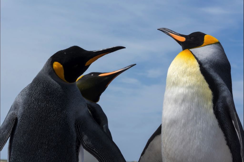
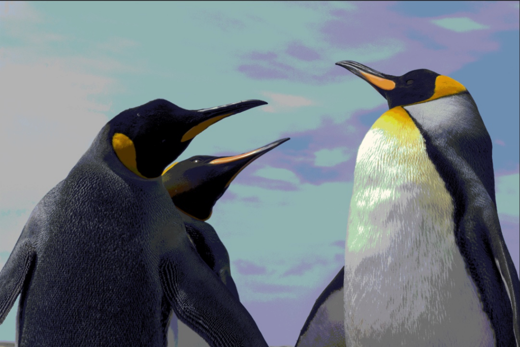
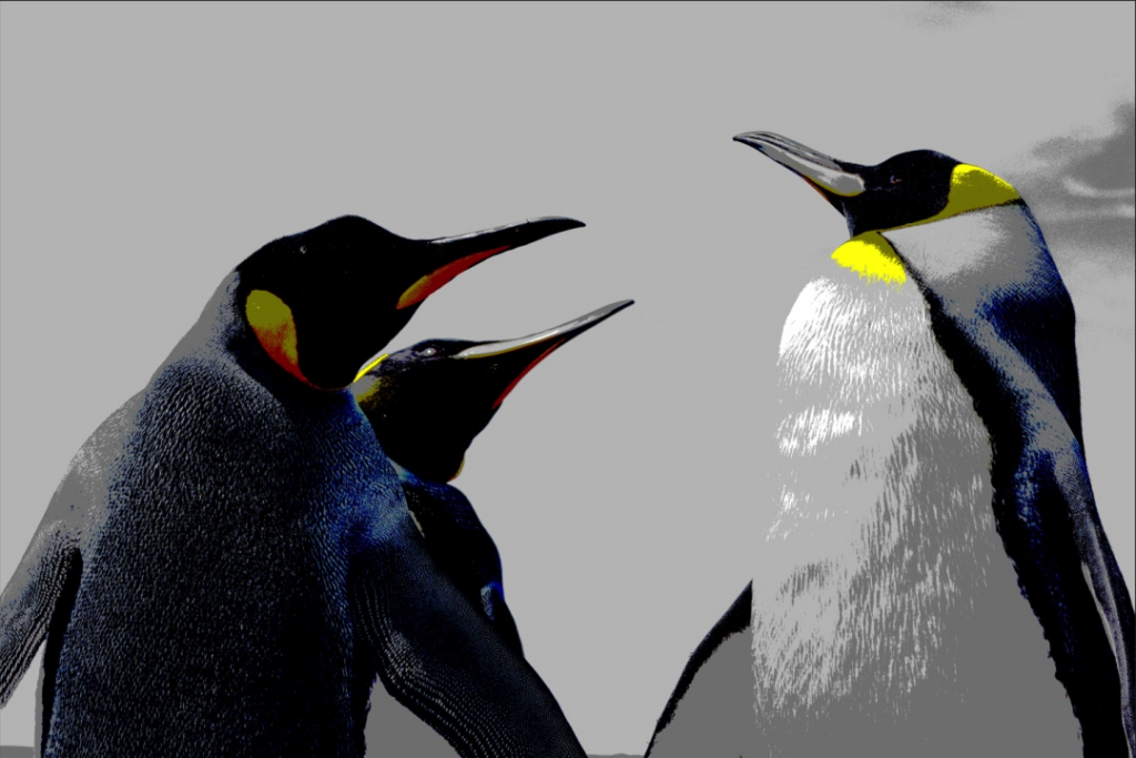
In Figure 1, the nuances of colors are displayed for the sky, clouds, and penguins. The tonal gradation is smooth. The body part is distinguished from the background. In Figure 2 and Figure 3, the image bit depth becomes lower, and fewer colors are used. Some nuances of the colors are omitted. The colors get mixed up or have sharp tonal changes. The figures look wired. One thing you need to know is that 24-bit is not the upper limit of image bit depth. You can set the image bit depth to 30 bits (10-bit channel bit depth), 36 bits (12-bit channel bit depth), or even higher values.
After you see the differences among these figures, you may wonder whether we should use a high bit depth in all circumstances.
The answer is no.
Though a high image bit depth brings vivid colors, it also poses requirements on large storage capacities, high bandwidths, and therefore high costs and good performance of software and hardware. In most scenarios, 24-bit image bit depth is enough. The 24-bit image bit depth constructs a color space that contains about 16.77 million colors, which is more than the number of colors human eyes can capture. Therefore, 24-bit image bit depth is most widely used.
So far, we have talked about image bit depth. In the next section, we will discuss several other concepts.
Image width, height, and stride
Let’s review a sentence at the beginning of this article. “A pixel is the smallest element in an image. Therefore, the storage of video images is essentially the storage of pixels.” This means that, based on image bit depth, we can calculate how many bytes are required to store the data of a pixel. Then, we can instruct computers to read this amount of data in a quantitative manner.
Pixels are displayed in rows in images and stored in rows in memories. When computers read image data, they read the data of pixels row by row. Therefore, computers must be informed of the following two things: the number of pixels in a row and the number of bytes required to read the pixel data in a row. To help computers figure out the numbers, the following three concepts are introduced: image width, height, and stride.
Image width and height
When it comes to image width and height, the first thing you think of may be a length unit such as a centimeter or inch. However, for computers, this is not the case. When computers process video images, they measure the width and height of images by counting the number of pixels, which is called the resolution.
We have not discussed resolutions in previous articles, but you may have seen resolutions in your life. When you watch videos on streaming platforms, scan images on image platforms, and read the specifications of videos or images, you see words like 540 × 960 (540P), 720 × 1280 (720P), and 1080 × 1920 (1080P). These words are what we call resolutions. A resolution determines the number of pixels in each row and each column of an image.
- Image width: determines the width of a resolution, which is the number of pixels in each row.
- Image height: determines the height of a resolution, which is the number of pixels in each column.
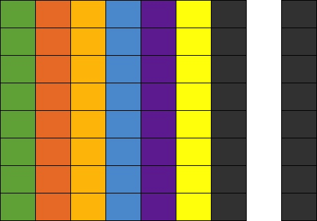
For an RGB image whose resolution is 540 × 960, each row has 540 RGB pixels and each column has 960 RGB pixels. The following figure shows the details.
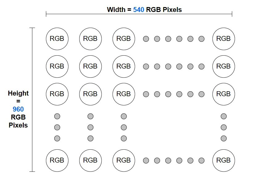
If we multiply image width by image height, the result is the total number of pixels in an image. In this example, the image has 518,400 (540 × 960) pixels. The higher the resolution is, the more pixels an image has.
This is the relationship among resolutions, image width, image height, and the number of pixels. In the follow-up articles, we will have further discussions about resolutions.
After computers figure out the number of pixels in each row by reading the resolution information, they need to calculate the number of bytes in each row. During video image processing, computers process data of images row by row. Thus, they pay more attention to the bytes in each row, but less to the number of rows, which is the image height.
Take an RGB image of 24-bit image bit depth as an example. The values of each channel in all pixels are continuously stored on the same plane. For more information, see Color and Color Space (Part II). If the resolution of the image is 538 × 960, you can calculate the number of bytes in each row in the following way:
- Number of pixels in each row = Image width = 538
- Number of bytes in each row = Image bit depth × Number of pixels in each row = (24 × 538)/8 = 1,614 (Note: 1 byte = 8 bits)
We can conclude that an RGB image whose resolution is 538 × 960 has 1,614 bytes of data in each row. The calculation seems right. However, if we tell a computer the number 1,614 when the computer reads an image whose resolution is 538 × 960, the following problem may occur:
Figure 5: original image (resolution: 538 × 960)

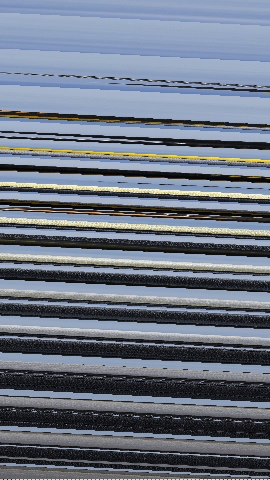
As shown in Figure 6, the rendered image contains dozens of diagonal lines and is completely different from the original image.
Why does this happen? Is there something wrong with the computer, or is the image width not the number of pixels in each row? To find out the answer, we have to know another concept: image stride.
Image stride
Most computers use a 32-bit or 64-bit processor. When the processor performs operations, the preferable data volume read at one time is a multiple of 4 bytes or 8 bytes. If you want the computer to read data that is not 4-byte or 8-byte aligned, the data must be processed at first. This obviously affects efficiency and performance. To prevent such an issue, extra data is added to the original data, so that the data to be processed is 4-byte or 8-byte aligned. This way, the computer can work with high efficiency. However, data alignment is more than 4-byte or 8-byte alignment. You can determine the alignment rule based on the actual hardware and software systems.
If you examine the calculated number 1,614 in the preceding section, you may find that
1,614 is not a multiple of 4 or 8. Therefore, if the image is stored in a system memory that requires 4-byte or 8-byte aligned data, extra data needs to be added to the image so that 1,614 bytes are aligned to, for example, 1,616 bytes. In this case, the stride of the image is 1,616 bytes.
The stride indicates the actual size in bytes of one row of pixels in memory and is greater than or equal to the number of bytes calculated based on the width of the image. When the number of bytes that equals a stride is read, the system continues reading the next row of pixels because one row of pixels of the image is read. The extra data that is added to form a stride is called padding. Padding affects how the image is stored in memory, but does not affect how the image is rendered.
The following figure represents the relationship among the width, padding, and stride.
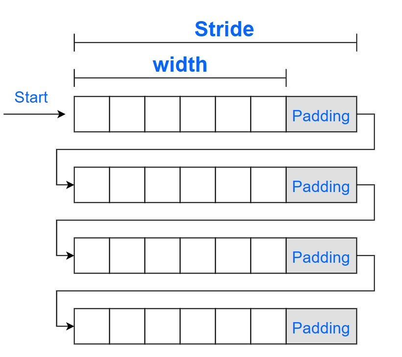
The figure shows that a computer reads an image from the position marked with Start. The image can be presented as expected only if the computer reads each row of pixels based on the stride and renders the image based on the width so that the padding does not affect the image rendering. If the computer renders the image based on the width rather than the stride, partial padding bytes may be rendered as valid image data. For example, you set the stride to 1614 in the preceding case. Then, the relative position of pixels between rows is cumulatively changed, which may cause abnormalities such as diagonal lines in the image.
You can understand the cause of diagonal lines in a simplified way.
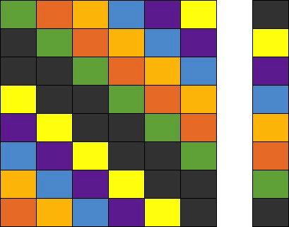
In the following figure, pixels rather than bytes are used to measure both the image data and the padding data so as to simplify the logic. For example, the pixels of the original image are calculated based on the following equation: Width x Height = 6 x 8. To align the data, set the stride to 8 for storing the image. The non-black and non-white colored part on the left side of the figure indicates valid image data, while the black colored part on the right side of the figure represents the padding. The white colored part is used to better distinguish the two parts.
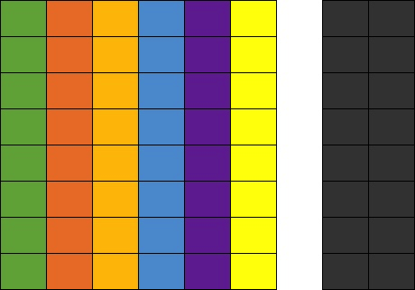
If the computer reads the image based on the stride that is 8 pixels, and renders the image based on the width that is 6 pixels, the non-black and non-white colored part of the figure can be presented, and the black and white colored part is ignored during image rendering.
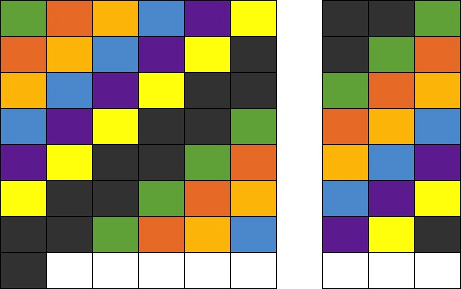
If you set the stride to 7 pixels and specify that the system still renders the image based on the width that is 6 pixels, the following issues occur: From the first row, the computer reads only 7 pixels with one pixel of the padding ignored. The ignored pixel is read as the first pixel in the next row, and the rest of the pixels are accordingly read and arranged. When the computer renders the image based on the width of 6 pixels, diagonal lines that run towards the lower-right corner appear, as shown in the following figure.
If you set the stride or width to an improper value, the reading and rendering of the image are affected. Therefore, make sure that you set a proper value for the stride and width. The following figures show the presented images when you set a greater value for the stride or width.
In actual practice, if the padding is accidentally rendered, the colors of the padding pixels vary based on the default color value used for padding. If the color value 0 is used for padding, the padding color of the RGB image is black, while that of the YUV image is green. For other situations where abnormal image reading and rendering may occur, you can try and take tests as needed.
Stride and width in the planar YUV format
The preceding illustration of the width and stride is made based on RGB images. In an RGB color space, the components reside on the same plane and are stored in a continuous way. The width and stride of an RGB image are considered on the same plane.
The YUV format is special in that the planar YUV format and the semi-planar YUV format can be used to store images. For more information, see Color and Color Space (Part II).
In a YUV image, each row also contains 720 pixels, which indicates the width of the image. From the perspective of image storage, the Y, U, and V data is separately stored on different planes. To present a YUV image, the computer must be informed of the size of data to read on each plane at a time. This way, a row of pixels of the original image can be read and presented as expected.
The size of data to read on each plane at a time means that the width and stride of each plane are required. The width and stride of the plane of each YUV component may vary because subsampling may be conducted for the U and V components. Therefore, the width and stride must be calculated based on different storage rules.
Common YUV formats are used as examples of how to understand the width and stride of each plane, including I422, I420, and NV21.
In the following examples, a channel bit depth of 8 bits is used, and the resolution of the image is 720 pixels in width and 1280 pixels in height. To facilitate understanding and simplify the calculation process, we assume that the processor supports 4-byte aligned data. If the width of a plane measured in bytes is a multiple of 4, the width can be used as the stride without the need for padding.
For more information about the sampling and storage principles of the I422, I420, and NV21 formats, see Color and Color Space (Part II). The following part provides only simple explanations of these principles.
The I422, I420, and NV21 formats all maintain full sampling for the Y plane. Therefore, we can conduct calculations for the Y plane at first.
For the Y plane, the following equations are provided to calculate the width and stride:
- Width_Y_Plane = Number of Y components in each row = Number of pixels in each row = Width = 720
- Stride_Y_Plane = Width_Y_Plane x Channel bit depth = Width_Y_Plane × 8 bits = 720 bytes
Note: In this example, Width_Y_Plane can be used as Stride_Y_Plane because the width of the Y plane measured in bytes, which is 720 bytes calculated by multiplying Width_Y_Plane with 8 bits, meets the predefined data alignment requirement. In actual scenarios, you need to check whether the width can be used as the stride based on calculations. Similar calculation processes are not repeated in the following part.
The sampling and storage logic on the U and V planes varies based on different types of YUV formats. The calculation must be conducted based on specific rules.
I422
The following information describes the sampling and storage logic of the I422 format:
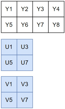
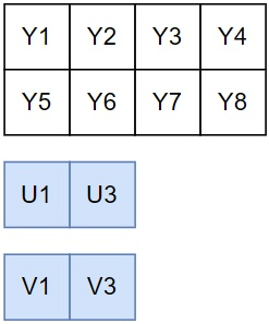
- Sampling: Y components are fully sampled. Horizontally, every two Y components share a set of U and V components. Vertically, U and V components are independently sampled for each row.
- Storage: Y, U, and V components are independently stored on three planes. For a sampling area with a width of 4 pixels and a height of 2 pixels, the Y, U, and V planes respectively contain 4×2, 2×2, and 2×2 arrays.
In each row, one U component is sampled for every two Y components. Therefore, the following equations are provided to calculate the width and stride on the U plane:
Width_U_Plane = Number of U components in each row = Number of pixels in each row/2 = Width/2 = 360
Stride_U_Plane = Width_U_Plane × Channel bit depth = 360 bytes
The V plane shares the same sampling and storage logic as the U plane. The following equation is provided to calculate the stride and width of the V plane:
Stride_V_Plane = Width_V_Plane × Channel bit depth = 360 bytes
If the array Stride_I422[3] is used to record the stride measured in bytes on the three planes, the following equation exists: Stride_I422[3] = {Width, Width/2, Width/2}. Width indicates the pixel width of the image.
I420
The following information describes the sampling and storage logic of the I420 format:
- Sampling: Y components are fully sampled. In the horizontal and vertical directions, every four Y components share a set of U and V components. That is, the second row follows the sampling logic of the first row.
- Storage: Y, U, and V components are independently stored on three planes. For a sampling area with a width of 4 pixels and a height of 2 pixels, the Y, U, and V planes respectively contain 4×2, 2×1, and 2×1 arrays.
In each row, one U component is sampled for every two Y components. Therefore, the following equations are provided to calculate the width and stride on the U plane:
Width_U_Plane = Number of U components in each row = Number of pixels in each row/2 = Width/2 = 360
Stride_U_Plane = Width_U_Plane × Channel bit depth = 360 bytes
The V plane shares the same sampling and storage logic as the U plane. The following equation is provided to calculate the stride and width of the V plane:
Stride_V_Plane = Width_V_Plane × Channel bit depth = 360 bytes
If the array Stride_I420[3] is used to record the stride measured in bytes on the three planes, the following equation exists: Stride_I420[3] = {Width, Width/2, Width/2}.
NV21
The following information describes the sampling and storage logic of the NV21 format:
- Sampling: Y components are fully sampled. In the horizontal and vertical directions, every four Y components share a set of U and V components. That is, the second row follows the sampling logic of the first row.
- Storage: Two planes are used with Y components stored on one plane and U and V components on the other plane. For a sampling area with a width of 4 pixels and a height of 2 pixels, the Y plane contains a 4×2 array, and the UV plane contains a 4×1 array. Swapped U and V components are stored on the same plane.
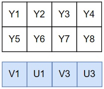
In each row, the sampling ratio between the U or V component and the Y component is 1:2. Therefore, the following equations are provided to calculate the width and stride on the UV plane:
- Width_UV_Plane = Number of U components in each row + Number of V components in each row = Number of pixels in each row/2 + Number of pixels in each row/2 = Width = 720
- Stride_UV_Plane = Width_UV_Plane × Channel bit depth = 720 bytes
If the array Stride_NV21[2] is used to record the stride measured in bytes on the two planes, the following equation exists: Stride_NV21[2] = {Width, Width}.
It is worth mentioning that for the I422, I420, and NV21 formats, the stride for each data read is twice the width of the image with all planes taken into consideration.
- Stride_I422[0] + Stride_I422[1] + Stride_I422[2] = Width x 2
- Stride_I420[0] + Stride_I420[1] + Stride_I420[2] = Width x 2
- Stride_NV21[0] + Stride_NV21[1] = Width x 2
However, for the I420 and NV21 formats, the data that is read from one row on the U/V plane or UV plane is shared with data that is read from two rows on the Y plane due to the sampling logic of the I420 and NV21 formats, which means that in the horizontal and vertical directions, every four Y components share a set of U and V components. Therefore, on average, the total amount of data to read for the image varies based on different formats.
- Data_I422 = Data_Y + Data_U + Data_V
= Height x Width + Height x Width/2 + Height x Width/2
= Height x Width x 2
- Data_I420 = Data_Y + Data_U + Data_V
= Height x Width + Height/2 x Width/2 + Height/2 x Width/2
= Height x Width x 1.5
- Data_NV21 = Data_Y + Data_UV
= Height x Width + Height/2 x Width
= Height x Width x 1.5
The preceding statistics show that the amount of data to read for the I422 formatted image is larger than that of the I420 and NV21 formats. This also proves that compared with the I422 format, the I420 format has a smaller amount of sampled data and a higher compression ratio.
Summary
Calculation methods of the width and stride in the common YUV formats are described in the preceding part. If you have difficulties understanding the methods, you can review Color and Color Space (Part II) to have a better understanding of the related knowledge. It needs to be reemphasized that, in the preceding examples, the stride calculated based on the width meets the alignment requirements, and thus padding is not required. This helps facilitate your understanding. In actual scenarios, you need to check whether padding is needed based on the operating system and hardware chips that you use.
At this point, you may have a certain understanding of how computers correctly read video image data in a quantitative manner. To figure out all quantifying rules for data reads is difficult considering the diversity of hardware chips, operating systems, and sampling and storage formats of color spaces.
ZEGOCLOUD’s engines are adapted to mainstream platforms and systems. After you integrate ZEGOCLOUD’s SDKs to develop audio and video applications, you can perform the capture, processing, conversion, and rendering of video images by using the SDKs. This frees you from the tedious side issues and helps you focus on the design and implementation of your business. To fulfill your personal requirements, ZEGOCLOUD’s SDKs also support custom video capture, which allows you to collect and process the original video image data as needed. This meets the requirements for specific sources, such as screenshot capture, and advanced video pre-processing, such as face beautification. You need to only import the collected and processed data into the SDKs through the specified port.
Before you use the custom video capture feature, make sure that you fully understand the concepts explained in the preceding sections, including color spaces, sampling and storage formats, and the width and stride. Otherwise, you may encounter abnormalities such as diagonal lines in the image.
Let’s Build APP Together
Start building with real-time video, voice & chat SDK for apps today!
